Since I don't work Fridays, this is the end of my second week commuting to work fifteen miles each way. Two things have definitely made the car more fun to drive. 1. The batteries are broken in so I have more current to work with and more importantly 2. I've learned some of the tricks to driving the car.
The biggest trick involves starting from a dead stop. Apparently, the AC motor feels like it has more torque at non-zero RPMs (perhaps just a false perception). However, if I start from a stoplight in the same way as a gasoline vehicle (rev the engine and slowly let out the clutch), I can start much more quickly than if I just leave the clutch out and floor the accelerator from a stopped motor. The same thing helps when starting from stopped on a hill.
With the charger plugin at both work and home, the PakTrakr fuel gauge doesn't seem to drop below the 80% mark, so I think the batteries will last a little while. The DC-DC converter is still working fine, so the car is actually quite convenient to drive. I haven't touched my gasoline car in two weeks now.
Sooooo, with everything working reasonably well------ it's time to drop the motor/tranny again and revisit the flywheel vibrations again. (doh!) I called around to several Porsche repair shops and finally found Dan Hall's Auto Machine. Apparently Dan is the only guy in the Portland area that has a flywheel balancer with a small enough mandrill to fit the 914 flywheel hole (1/2 inch or so). While I hesitate to dismantle a working car, I'd really like to rev the motor safely up to 7000-8000 RPM to get more torque and run the car on the freeway in second gear (!).
I contacted Azure Dynamics and asked them how I could measure the RPM on the motor so I could drive the tachometer in the middle of the dash. They strongly recommended against tapping into the encoder signals since they had noise issues themselves with the encoder signals. With the motor out, I'm going to look into RPM kits for electric cars that use spinning magnets on the flywheel with a magnetic sensor to generate a signal. Stay tuned...
Thursday, September 13, 2007


Tuesday, September 11, 2007
A Response from CC Power on the DC-DC
I just got an e-mail back from Electro Automotive from CC-Power regarding the failed DC-DC converter. I prefer not to comment on it but simply wish to pass it on to others who might have wondered what the manufacturer said. Here goes:
"The converters have been manufactured for over 20 years and we have 10,000+ units operating in South Africa at 120 volts, all using the same build, without any problems.
"The existing current limit system operates on a pulse by pulse basis and shuts the converter off immediately current exceeds a safe level. The method Kutscha is using has been tried and thrown out as it is not fast enough to protect the devices in an over-current situation. It also effects the transient response of the converter, causing the voltage to dip when load is increased and overshoot when load is removed."
"The problems he is experiencing are almost certainly voltage related than high current and are due to his installation, rather than the operation of the converter."
"The converter should be connected directly to the battery terminals. if he is connecting to the controller terminals, the problems of over voltage during regeneration will be much greater."
(okay one comment: no wonder the parts in this unit are so ancient! 20 years?!)
Cheers,
Tim
"The converters have been manufactured for over 20 years and we have 10,000+ units operating in South Africa at 120 volts, all using the same build, without any problems.
"The existing current limit system operates on a pulse by pulse basis and shuts the converter off immediately current exceeds a safe level. The method Kutscha is using has been tried and thrown out as it is not fast enough to protect the devices in an over-current situation. It also effects the transient response of the converter, causing the voltage to dip when load is increased and overshoot when load is removed."
"The problems he is experiencing are almost certainly voltage related than high current and are due to his installation, rather than the operation of the converter."
"The converter should be connected directly to the battery terminals. if he is connecting to the controller terminals, the problems of over voltage during regeneration will be much greater."
(okay one comment: no wonder the parts in this unit are so ancient! 20 years?!)
Cheers,
Tim
Sunday, September 9, 2007
DC-DC Seems to Work!
I just drove home from a meeting for half an hour with the headlights on. In the process of driving, the brake lights and turn-signals were also on. This is the first time I've arrived home with the DC-DC converter still working! Yay! I'm going to give it a week and see if anything else causes a failure. In the meantime, I'm going to report my findings to CCPower and Mike at ElectroAuto so perhaps they can modify the design.
Many thanks to all of the analog EE types out there who offered assistance in helping me understand just what the heck was going on with this thing. I've learned a tremendous amount about switching power supplies, shunts, protection circuits and over-current sensors.
If all works out this week, I'd like to start working on two fun things. The first is a simple op-amp circuit that drives the analog fuel gauge to show the pack voltage (maybe swings from 120V to 155V for a nominal 144V pack?). The second is an opto-isolated circuit to capture the encoder pulses off the AC motor to drive the large RPM gauge in front of my nose that doesn't seem to do anything. Let's cross our fingers and hope the DC-DC holds out.
Cheers,
Tim
Many thanks to all of the analog EE types out there who offered assistance in helping me understand just what the heck was going on with this thing. I've learned a tremendous amount about switching power supplies, shunts, protection circuits and over-current sensors.
If all works out this week, I'd like to start working on two fun things. The first is a simple op-amp circuit that drives the analog fuel gauge to show the pack voltage (maybe swings from 120V to 155V for a nominal 144V pack?). The second is an opto-isolated circuit to capture the encoder pulses off the AC motor to drive the large RPM gauge in front of my nose that doesn't seem to do anything. Let's cross our fingers and hope the DC-DC holds out.
Cheers,
Tim
DCDC Transistor Hack
After talking with various people and realizing that the over-current circuitry was making the FET gate pulses way too large, I decided to hack the DC-DC converter circuit.

Here's the new circuit (click to enlarge). I swapped out the IRFP350 FETs with IRFP460 FETs which have a higher voltage and current rating. To compensate for the larger gate capacitance and speed up the rise/fall time of the FET gates, I lowered the gate resistance from 27 ohms to 15 ohms.
The biggest hack, though, is tying the nShutdown pin to ground (disabling it) and adding a 2N3904 NPN transistor to bleed voltage off the soft-start capacitor when current is sensed too high. This makes a crude overcurrent sensor that limits the FET gate pulse without all the problems with pulsing the nShutdown pin. I adjusted the "amp adjust" potentiometer and was able to get the FET gate pulse to shrink if too much current was pulled.

Here is the top of the board. I've tied the emitter and collector of the 2N3904 to the leads of the soft-start capacitor. The base of the transistor is stretched to the left and goes down through a hole I drilled in the printed-circuit board.

Here's the back side of the circuit-board. I kept the .01uF capacitor to filter out the pulses on the current sensor and tied the lead of the 2N3904 (coming out through the hole) to the tap on the potentiometer. Note that I cut the trace just below the hole which originally tied the over-current circuit to the nShutdown pin, which I grounded with a large solder blob just to the right of the hole.
For the final test, I installed the unit back in the 914 EV, turned on the ignition and turned on all the accessories. The DCDC seemed to handle the current reasonably well without heating up much. The real acid test will be to drive around at night with the headlights on and see if the DC-DC fails again. Things look promising so far. I'm a bit miffed that CCPower could have solved this issue themselves with a cheap (69cents from Radio Shack, cheaper in bulk) transistor. I'll be driving around after dark this evening and will keep y'all posted.

Here's the new circuit (click to enlarge). I swapped out the IRFP350 FETs with IRFP460 FETs which have a higher voltage and current rating. To compensate for the larger gate capacitance and speed up the rise/fall time of the FET gates, I lowered the gate resistance from 27 ohms to 15 ohms.
The biggest hack, though, is tying the nShutdown pin to ground (disabling it) and adding a 2N3904 NPN transistor to bleed voltage off the soft-start capacitor when current is sensed too high. This makes a crude overcurrent sensor that limits the FET gate pulse without all the problems with pulsing the nShutdown pin. I adjusted the "amp adjust" potentiometer and was able to get the FET gate pulse to shrink if too much current was pulled.

Here is the top of the board. I've tied the emitter and collector of the 2N3904 to the leads of the soft-start capacitor. The base of the transistor is stretched to the left and goes down through a hole I drilled in the printed-circuit board.

Here's the back side of the circuit-board. I kept the .01uF capacitor to filter out the pulses on the current sensor and tied the lead of the 2N3904 (coming out through the hole) to the tap on the potentiometer. Note that I cut the trace just below the hole which originally tied the over-current circuit to the nShutdown pin, which I grounded with a large solder blob just to the right of the hole.
For the final test, I installed the unit back in the 914 EV, turned on the ignition and turned on all the accessories. The DCDC seemed to handle the current reasonably well without heating up much. The real acid test will be to drive around at night with the headlights on and see if the DC-DC fails again. Things look promising so far. I'm a bit miffed that CCPower could have solved this issue themselves with a cheap (69cents from Radio Shack, cheaper in bulk) transistor. I'll be driving around after dark this evening and will keep y'all posted.
Saturday, September 8, 2007
I Blew it Again! Learning About Soft-Start...
After studying the oscilloscope waveforms, I believed that the current sense circuit was way too spikey. This is the "amp adjust" potentiometer output in the C400 schematic. I found that the inductive spikes were shutting off the DC-DC converter through the nShutdown pin on the SG3525A and causing craziness in the gate-drive pulse. Soooo, I picked a reasonable (.01uF) capacitor to filter out the current sense waveform and remove the inductive spikes.

Here's the .01uF capacitor soldered to the board across the "Amp Adjust" potentiometer output.

If you compare the voltage spikes in this scope view to the one in the previous post, the inductive spikes are still there, but not as prominent.

Here's the same view under a 7 amp load. Note the gate drive pulse at the bottom of the screen has widened out to 8usec. The inductive spikes are much smaller and don't trigger the nShutdown circuit.
At this point when I apply just over a 14 amp load, the current sense circuit pulses are high enough to trigger the nShutdown pin on the SG3525A. When this happens, I note that the output voltage drops because we are in current limiting mode (good). However, the FET gate pulse is all over the place and the DC-DC converter whines loudly. This is important to remember after you read the next section...
I turned down the current limit to 14 amps and re-installed it in the 914 EV. After powering up the car, the unit didn't blow. I turned on the headlights and the system kept working. I then turned on the fog lights, tail lights, turn-signals and reverse lights. The DC-DC started whining loudly as stated in the previous paragraph. I thought this was good because I figured it was in current limiting mode. However, after a few seconds, the system went silent and, as I feared, I had blown the FETs again.... (sigh).
After taking a break, I read some textbooks and analyzed the SG3525A circuit diagrams once more. I'm going to take a wild guess that this is what happened (for all you advanced EE geeks):
When the unit goes into overcurrent mode, it pulses the nShutdown signal which immediately turns off the output gate drive. This causes the output voltage to lower and the inverting input from the opto-coupler to fall, increasing the duty cycle of the gate-drive. What I find on the oscilloscope in over-current mode is that the PWM output to the gate drive jumps wildly from 0-100%. This clearly puts the primary coils of the transformer into saturation mode and stresses the drive FETs.
After much textbook research, I believe that the overcurrent circuit should quickly bleed voltage off the soft-start capacitor without quickly turning off the output PWM pulse to prevent the PWM pulse from going above a certain limit. What we want is to have the gate-drive pulse change its state smoothly instead of wildly jumping all over the place.
A good example of how this is done is shown at:
http://www.edaboard.com/ftopic153496.html
If you look at the schematic halfway down the page, the overcurrent sensing circuit draws down the soft-start capacitor and doesn't drive the nShutdown pin as in the CCPower schematic.
I'm going to try and alter this circuit with a pull-down transistor and put it into overcurrent to see if the gate-drive oscillates or simply maxes out.
This is one hell of a learning experience, especially for a digital engineer like myself.
Goodnight.

Here's the .01uF capacitor soldered to the board across the "Amp Adjust" potentiometer output.

If you compare the voltage spikes in this scope view to the one in the previous post, the inductive spikes are still there, but not as prominent.

Here's the same view under a 7 amp load. Note the gate drive pulse at the bottom of the screen has widened out to 8usec. The inductive spikes are much smaller and don't trigger the nShutdown circuit.
At this point when I apply just over a 14 amp load, the current sense circuit pulses are high enough to trigger the nShutdown pin on the SG3525A. When this happens, I note that the output voltage drops because we are in current limiting mode (good). However, the FET gate pulse is all over the place and the DC-DC converter whines loudly. This is important to remember after you read the next section...
I turned down the current limit to 14 amps and re-installed it in the 914 EV. After powering up the car, the unit didn't blow. I turned on the headlights and the system kept working. I then turned on the fog lights, tail lights, turn-signals and reverse lights. The DC-DC started whining loudly as stated in the previous paragraph. I thought this was good because I figured it was in current limiting mode. However, after a few seconds, the system went silent and, as I feared, I had blown the FETs again.... (sigh).
After taking a break, I read some textbooks and analyzed the SG3525A circuit diagrams once more. I'm going to take a wild guess that this is what happened (for all you advanced EE geeks):
When the unit goes into overcurrent mode, it pulses the nShutdown signal which immediately turns off the output gate drive. This causes the output voltage to lower and the inverting input from the opto-coupler to fall, increasing the duty cycle of the gate-drive. What I find on the oscilloscope in over-current mode is that the PWM output to the gate drive jumps wildly from 0-100%. This clearly puts the primary coils of the transformer into saturation mode and stresses the drive FETs.
After much textbook research, I believe that the overcurrent circuit should quickly bleed voltage off the soft-start capacitor without quickly turning off the output PWM pulse to prevent the PWM pulse from going above a certain limit. What we want is to have the gate-drive pulse change its state smoothly instead of wildly jumping all over the place.
A good example of how this is done is shown at:
http://www.edaboard.com/ftopic153496.html
If you look at the schematic halfway down the page, the overcurrent sensing circuit draws down the soft-start capacitor and doesn't drive the nShutdown pin as in the CCPower schematic.
I'm going to try and alter this circuit with a pull-down transistor and put it into overcurrent to see if the gate-drive oscillates or simply maxes out.
This is one hell of a learning experience, especially for a digital engineer like myself.
Goodnight.
Debugging the DC-DC waveforms
I spent most of Friday trying to figure out just what was blowing the DC-DC converter.

Here's my full testbench setup. On the upper left, I have a 156V DC power supply. On the lower-left sits a 12V battery to act as an accessory battery. The 30Mhz $400 oscilloscope sits ready. The opened up DC-DC converter is front and center. I have the oscope covered with cardboard to shield out excess light so I can take pictures of waveforms. I actually used the aluminum case for the DC-DC converter as a camera stand so that I could turn off the flash which causes too much glare on the oscope screen.

Here's a close-up view of the 156V power supply. In essence, I took five 31.2 volt power supplies from HP inkjet printers and hooked them up in series. I broke off the grounding pin of all the power cords except the bottom supply so that the output stage could float and allow the series connection. These supplies put out 2.5 amps, so this ought to provide 375 watts of power if I need it for testing.

Okay, here's the first scope trace. I removed the blown FETs and simply measured Vgs at the missing part location. Dimensions are 5us/div and 5V/div. It looks like we have a period of 30us and the power supply for the SG3525A is 12 volts. Without the FETs in place the controller drives both FETs in push-pull configuration at their full duty cycle. There's actually a dead time of about 0.6us between the high states on the gate-drive pulses.

I've just soldered in two IRFP460 FETs (still with no load on the output) and here's what the gate-drive looks like. The pulse from the SG3525A is on the bottom and the actual Vgs voltage at the FET is the top waveform. The IRFP460 part has a larger gate capacitance than the original IRFP350 parts, so the charge and discharge slope doesn't look so great. Perhaps I could reduce the resistance of the gate-drive resistors to help with this. The FETs are still cold with no load. With the FET in place, the drive pulse shortens to 0.9us. Dimensions are 0.5us/div and 5V/div.

Here's where things get interesting. I'm now measuring the drain-source voltage on one of the FETs (Vds) with no output load. Dimensions are 20us/div and 50V/div. Without any load, the voltage swings on the FETs are twice the input voltage (about 312 volts) plus any ringing from inductor kick-back! One of the disadvantages of the push-pull architecture is that the driving transistors need to handle twice the input voltage.
The far left of the screen shows one FET turning off and letting the voltage oscillate. The two high spikes near the right edge of the screen show the voltage across the first FET as the second FET turns on. There's even over-voltage from the inductive ringing. If the input voltage goes up to 170V with charging and regenerative braking, the FETs need to handle at least 340 volts plus the ringing voltage, which is typically even higher... (yikes!)
I've added the 12V accessory battery as an output load and let things settle. This picture shows the gate drive (Vgs) of one FET (bottom left) and the resulting source-drain voltage (Vds) on the opposite FET. Time dimension is 5us/div. Note that the pulses going to the FET gates are 15us apart, causing the snap to a low voltage three divisions into the display. The Vgs pulse is still about 1.2 usec wide.

Here's the same image as above, but with a 7 amp load. The SG3525A is now pulsing the FETs much more often to handle the load. The gate-drive pulses are now 8us wide and the drain-source voltages are clearly jumping from zero volts to 156 volts to 312 volts.
The circuit controlling this pulse width is the opto-coupler feedback going into the inverting input on the SG3525A. As the load increases, the main output voltage tends to drop, telling the 741 op-amp to turn off the 4N25 opto-coupler. With the opto-coupler off, the inverting input for the error amplifier in the SG3525A falls and increases the pulse width. (See schematic in previous blog posting)
What boggles me about this picture is that this DC-DC converter was supposed to put out 400 watts. That's about 28 amps. Just pulling 7 amps causes the gate drive pulse width to increase to 8us which is over half of the available 15us time that they can be on. If I add another 7 amp load, the gate pulse width extends out to its full width of 15us and then the waveforms go a bit nuts. It seems to me that if we run out of controllable pulse width at 14 amps, then the controller has no way of providing anywhere near 28 amps. Hmm....

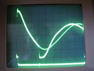
Another circuit I analyzed was the amperage control circuit. This circuit captures current going through the isolation transformer and converts it to voltage pulses. If these pulses get too high then the SG3525A controller should turn off the FET gate drives to prevent them from overheating. The top waveform in the above picture shows the voltage across the "Amps Adjust" potentiometer with just the 12V accessory battery load. Note that the primary signal shows nice rolling pulses; however, there are sharp spikes at every gate drive transition. These rolling pulses are supposed to control the nShutdown pin on the SG3525A controller. The unfortunate thing is that the actual voltage triggering the nShutdown pin are the voltage spikes. I believe the dimensions are 0.5V/div for the top waveform and 5us/div timebase.

Here's that same picture with a 7 amp load. The bottom waveform shows the FET gate drive pulses widening out to 8us and the voltage on the "amps adjust" pot show a much higher voltage (with much higher spikes too). I really need to get rid of those spikes.
I'm unsure of where to go next. It's clear to me that the 312 volts across the FETs along with the inductive kick-back spikes are running very near to the operating point of the FETs. At high current pulls, the inductive spikes are only going to get worse and tend to blow the FETs. I'm also concerned that a 7 amp load consumes just over 50% of the available pulse width modulation range for the gate-drive pulses, so we just can't supply more than about 13 amps without maxing out.
My first step is to try and reduce the inductive spiking. The only circuit provided for that is the C7/R16 capacitor/resistor pair between the FET drain posts. I found a great article on how to pick these values on the Maxim website here:
http://www.maxim-ic.com/appnotes.cfm/an_pk/3835
I also might add an RC filter to the "amps adjust" circuit to filter out the high-voltage spikes so that the nShutdown input gets a more accurate voltage.
I still haven't heard back from CCpower about this, but I'll give them a few more days. As you might imagine, I'm rather frustrated that I have to debug someone else's design. I'm not sure this component was meant for this application.

Here's my full testbench setup. On the upper left, I have a 156V DC power supply. On the lower-left sits a 12V battery to act as an accessory battery. The 30Mhz $400 oscilloscope sits ready. The opened up DC-DC converter is front and center. I have the oscope covered with cardboard to shield out excess light so I can take pictures of waveforms. I actually used the aluminum case for the DC-DC converter as a camera stand so that I could turn off the flash which causes too much glare on the oscope screen.

Here's a close-up view of the 156V power supply. In essence, I took five 31.2 volt power supplies from HP inkjet printers and hooked them up in series. I broke off the grounding pin of all the power cords except the bottom supply so that the output stage could float and allow the series connection. These supplies put out 2.5 amps, so this ought to provide 375 watts of power if I need it for testing.

Okay, here's the first scope trace. I removed the blown FETs and simply measured Vgs at the missing part location. Dimensions are 5us/div and 5V/div. It looks like we have a period of 30us and the power supply for the SG3525A is 12 volts. Without the FETs in place the controller drives both FETs in push-pull configuration at their full duty cycle. There's actually a dead time of about 0.6us between the high states on the gate-drive pulses.

I've just soldered in two IRFP460 FETs (still with no load on the output) and here's what the gate-drive looks like. The pulse from the SG3525A is on the bottom and the actual Vgs voltage at the FET is the top waveform. The IRFP460 part has a larger gate capacitance than the original IRFP350 parts, so the charge and discharge slope doesn't look so great. Perhaps I could reduce the resistance of the gate-drive resistors to help with this. The FETs are still cold with no load. With the FET in place, the drive pulse shortens to 0.9us. Dimensions are 0.5us/div and 5V/div.

Here's where things get interesting. I'm now measuring the drain-source voltage on one of the FETs (Vds) with no output load. Dimensions are 20us/div and 50V/div. Without any load, the voltage swings on the FETs are twice the input voltage (about 312 volts) plus any ringing from inductor kick-back! One of the disadvantages of the push-pull architecture is that the driving transistors need to handle twice the input voltage.
The far left of the screen shows one FET turning off and letting the voltage oscillate. The two high spikes near the right edge of the screen show the voltage across the first FET as the second FET turns on. There's even over-voltage from the inductive ringing. If the input voltage goes up to 170V with charging and regenerative braking, the FETs need to handle at least 340 volts plus the ringing voltage, which is typically even higher... (yikes!)

I've added the 12V accessory battery as an output load and let things settle. This picture shows the gate drive (Vgs) of one FET (bottom left) and the resulting source-drain voltage (Vds) on the opposite FET. Time dimension is 5us/div. Note that the pulses going to the FET gates are 15us apart, causing the snap to a low voltage three divisions into the display. The Vgs pulse is still about 1.2 usec wide.

Here's the same image as above, but with a 7 amp load. The SG3525A is now pulsing the FETs much more often to handle the load. The gate-drive pulses are now 8us wide and the drain-source voltages are clearly jumping from zero volts to 156 volts to 312 volts.
The circuit controlling this pulse width is the opto-coupler feedback going into the inverting input on the SG3525A. As the load increases, the main output voltage tends to drop, telling the 741 op-amp to turn off the 4N25 opto-coupler. With the opto-coupler off, the inverting input for the error amplifier in the SG3525A falls and increases the pulse width. (See schematic in previous blog posting)
What boggles me about this picture is that this DC-DC converter was supposed to put out 400 watts. That's about 28 amps. Just pulling 7 amps causes the gate drive pulse width to increase to 8us which is over half of the available 15us time that they can be on. If I add another 7 amp load, the gate pulse width extends out to its full width of 15us and then the waveforms go a bit nuts. It seems to me that if we run out of controllable pulse width at 14 amps, then the controller has no way of providing anywhere near 28 amps. Hmm....

Another circuit I analyzed was the amperage control circuit. This circuit captures current going through the isolation transformer and converts it to voltage pulses. If these pulses get too high then the SG3525A controller should turn off the FET gate drives to prevent them from overheating. The top waveform in the above picture shows the voltage across the "Amps Adjust" potentiometer with just the 12V accessory battery load. Note that the primary signal shows nice rolling pulses; however, there are sharp spikes at every gate drive transition. These rolling pulses are supposed to control the nShutdown pin on the SG3525A controller. The unfortunate thing is that the actual voltage triggering the nShutdown pin are the voltage spikes. I believe the dimensions are 0.5V/div for the top waveform and 5us/div timebase.

Here's that same picture with a 7 amp load. The bottom waveform shows the FET gate drive pulses widening out to 8us and the voltage on the "amps adjust" pot show a much higher voltage (with much higher spikes too). I really need to get rid of those spikes.
I'm unsure of where to go next. It's clear to me that the 312 volts across the FETs along with the inductive kick-back spikes are running very near to the operating point of the FETs. At high current pulls, the inductive spikes are only going to get worse and tend to blow the FETs. I'm also concerned that a 7 amp load consumes just over 50% of the available pulse width modulation range for the gate-drive pulses, so we just can't supply more than about 13 amps without maxing out.
My first step is to try and reduce the inductive spiking. The only circuit provided for that is the C7/R16 capacitor/resistor pair between the FET drain posts. I found a great article on how to pick these values on the Maxim website here:
http://www.maxim-ic.com/appnotes.cfm/an_pk/3835
I also might add an RC filter to the "amps adjust" circuit to filter out the high-voltage spikes so that the nShutdown input gets a more accurate voltage.
I still haven't heard back from CCpower about this, but I'll give them a few more days. As you might imagine, I'm rather frustrated that I have to debug someone else's design. I'm not sure this component was meant for this application.
Wednesday, September 5, 2007
Initial CCPower Schematic
In my efforts to debug the failures of the DC-DC converter, I tried to capture a schematic of the board. I didn't have time to create a component for the SG3525A controller, but all the pin numbers are listed. I replaced the IRFP350 FETs with IRFP460 FETs which have a higher isolation voltage and larger drive current; however, they also have about twice the gate capacitance, which I didn't think of.
Any suggestions for what could blow the FETs up would be helpful (please leave in comments section).

You can get a larger image by clicking on the thumbnail above.
Links to the various parts are:
IRFP350
IRFP460
SG3525A
The failing conditions are when the 12V accessories are drawing a lot of current (25 amps) and the output voltage has sagged down to 12V (DC-DC tries to put out 13.9V).
I'm guessing that as the voltage sags, the output (pin 6) of the 741 op-amp goes low and turns off the LED in the opto-coupler. With the opto-coupler off, the voltage goes low on pin1 of the SG3525A (inverting input to error amp) and increases the pulse widths going to the drive FETs. If the pulse widths are too long, they cause the FETs to stay on too long and saturate the inductors, which causes a high-current spike of +144V that blows the FETs.
Supposedly, the current sense loop voltage that is adjusted by the R8 potentiometer should send a positive pulse into pin10 of the controller to shut down the FETs, but this may not be happening quickly enough.
Initially, I cringed because there were no kick-back diodes in the circuit, but I think that C7 and R16 (2 watt resistor) send any kick-back currents into the opposite inductor when the FETs let go.
Any ideas? Thanks for your input.
Cheers,
Tim
Any suggestions for what could blow the FETs up would be helpful (please leave in comments section).

You can get a larger image by clicking on the thumbnail above.
Links to the various parts are:
IRFP350
IRFP460
SG3525A
The failing conditions are when the 12V accessories are drawing a lot of current (25 amps) and the output voltage has sagged down to 12V (DC-DC tries to put out 13.9V).
I'm guessing that as the voltage sags, the output (pin 6) of the 741 op-amp goes low and turns off the LED in the opto-coupler. With the opto-coupler off, the voltage goes low on pin1 of the SG3525A (inverting input to error amp) and increases the pulse widths going to the drive FETs. If the pulse widths are too long, they cause the FETs to stay on too long and saturate the inductors, which causes a high-current spike of +144V that blows the FETs.
Supposedly, the current sense loop voltage that is adjusted by the R8 potentiometer should send a positive pulse into pin10 of the controller to shut down the FETs, but this may not be happening quickly enough.
Initially, I cringed because there were no kick-back diodes in the circuit, but I think that C7 and R16 (2 watt resistor) send any kick-back currents into the opposite inductor when the FETs let go.
Any ideas? Thanks for your input.
Cheers,
Tim
Subscribe to:
Posts (Atom)
