Well, I'm back to square one again on the tranny. Rennsport Systems kept my transmission for over two months and didn't work on it. I asked the good folks over at 914world.com about the situation and most people suggested that I was waiting far too long and paying far too much for what I was doing. Two folks highly recommended I go out to the Rennsport shop without calling ahead of time and just take the transmission back, just to be sure they didn't start working on it as I drove over.
So that's what I did. Jeff at the shop was gracious enough to give me back the transmission (and the extra-parts tranny) without any questions. They seemed completely stressed out due to the extreme backlog of work, anyway.
I'm in the process of trying to buy a rebuilt tranny from one of the 914world folks, so I hope that pans out. My other option is to have "Dr. Evil" from 914world rebuild a transmission for me for $1500.
My gut feel, not based on any fact, is that a different transmission won't have the same resonant problem as this one does; however, it may come with its own problems. Stay tuned as the saga continues...
Friday, December 21, 2007
Sunday, November 25, 2007
Still waiting for the Transmission
Well, it's been over a month since I've posted since the holidays are here and I'm still waiting for the transmission to get back. I talked with a guy at Rennsport Systems last week and he said he'd see what was going on and get back to me. Still haven't heard from him. I'll try again tomorrow.
On a more positive note, Ross Cunniff got his 914 AC kit running recently and Bob has been making progress on his BMW 325i performance EV (see links at right).
I also had a phone interview with a journalist named Kristen that I met at NEDRA who's writing an EV conversion article for the February issue of SportsCarMarket.
In the meantime, I'm helping other folks using the AC kits with the Azure Dynamics controller get their systems working. Best wishes to all the EV conversions in progress.
Sunday, October 21, 2007
Hair Dryers Installed
I took a few hours today to get the small hairdryers installed.

In order to have a convenient switch to activate the hairdryers, I hijacked the defroster knob switch. I was lucky enough to have this option on my car. The wires from the defroster knob sit in their own plastic tube, so it was easy to find the yellow/red wire going towards the center wiring column of the car under the clutch pedal. This wire provides 12V when activated, just the thing I need to fire up the 12V DC relay.

Here's the travel hair-dryer attached to the heater intake on the passenger side of the car. The coupling is just short enough to let the hairdryer not interfere with the hood spring. The pipe clamps make the whole thing very snug.

Here's the DC relay mounted on the firewall just behind the middle battery box above the foot pedals. I used two 10-32 rivnuts to bolt this thing in. The two hair-dryers are tied into the terminals on the left. The negative battery cable is on the lower right (black wires) and the upper right comes from the positive battery post in the fuel compartment with an inline 10 amp blade fuse.
Remember the yellow/red wire from under the dash in the top picture? It's tied into the top coil terminal on the relay here. Since the chassis of the car is ground, I simply tied the bottom coil terminal to the mounting bolt (small blue wire).
For testing, I started with one hair dryer on the "low" setting with 5-amp fuse. It ran well (albeit loudly) and provided a slight warming into the cockpit. If I put the hairdryer on "high," the 5-amp fuse blows immediately. The hairdryer is very loud on "high" so I put both hair dryers on their "low" settings and used a 10-amp fuse. I suppose in desperate move to heat the cockpit, I could put in a 20-amp fuse and run one hair dryer on "high" since the high setting pulls about 15 amps. I'll try the "low" settings for now and see how it goes.
Next up: experimenting with an optocoupler to capture voltage for the "fuel gauge"
Friday, October 19, 2007
Serial Port and Hood Pin
Today was a bit slow. I received some AMP pins in the mail that fit the special connectors on the DMOC445 controller. To make the serial port more robust, I crimped the pins onto the ends of the 16-gauge wires and inserted them into the 8-position connector that came with the DMOC.

Here's the finished connector. It's far more reliable than the simple sockets I had soldered to the end of the cable. See this post for the prior implementation.

I also took a little time to install the hood pin that I got from Schucks yesterday. Drilling a rectangular hold through the engine compartment lid was very tricky. I covered up most of the rough edges with the plate that comes with the hood pin. At least it's a lot nicer than the block of wood I was using before.
Just for grins, I fitted one of the hair dryers to the passenger side heating duct and plugged into the wall outlet to see how well it would heat the car. It's rather loud, but produces a light stream of warm air. I wouldn't use this to fully heat the car, but it'll probably make a decent defroster.
Tuesday, October 16, 2007
Dedicated Charging Outlet and Hairdryer Coupling
After sleeping for 14 hours last night, I think I'm somewhat recovered from that nasty cold. I dropped by Parkrose hardware after work and picked up some stuff to install in the EV.

Since I have a gas range, I replaced the 240V breaker for the non-existant electric range with a 20-amp 120V breaker dedicated to charging the 914 EV.

I purchased two small travel hair dryers over the weekend and found some plumbing couplings that seem to fit quite well on both the hair-dryer and the heating system input. I forgot to bring the relay to the hardware store, so I'll probably get the electrical connectors tomorrow and install the system over the weekend.
I also ordered some of the custom sockets that go inside the 8-pin DMOC connector so that the serial port will be much more of a permanent installation instead of just sort of dangling out of the controller.
Big thanks to Ross Cunniff for pointing out that hood pins are available at the local auto-parts store. I searched high and low for these at the regular hardware store but didn't think to look in the "bling" (ahem, I mean performance) section of the auto store.
Monday, October 15, 2007
Running the AC24 at High RPM - maybe not
I'm still big-time sick today, but recovering quickly. In my efforts to understand the torque of the AC24 motor a bit more, I looked at the datasheet online at Azure Dynamics:
http://www.azuredynamics.com/pdf/AC24%202007.pdf
Hmm, it looks like the optimal operating point is really around 4500 RPM and torque drops off quite a bit at higher revs than that. In my frenzy to go on the freeway in first gear, I didn't really look at the operating characteristics of the motor. Also spinning the input shaft of the transmission above 4500 RPM continuously might wear it out sooner. Oh well, back to bed to recover...
Saturday, October 13, 2007
Initial Fuel Gauge Driver Schematic
Since I'm stuck indoors today to recover from a sore throat, I put together the following schematic to drive the fuel gauge based on the pack voltage.

(Click to enlarge the image)
With the exception of the 4N25 opto-isolator, which I salvaged from a dead UPS, all parts are available at Radio Shack. I hope to implement this soon. Comments and feedback are welcome.

(Click to enlarge the image)
With the exception of the 4N25 opto-isolator, which I salvaged from a dead UPS, all parts are available at Radio Shack. I hope to implement this soon. Comments and feedback are welcome.
Friday, October 12, 2007
Finishing the Serial Cable and Testing the Fuel Gauge
I had a bit more time today to work on some other small projects.

Here's the 914 patiently waiting for its rebuilt transmission from Rennsport Systems. It'll be awhile since Rennsport won't start on the rebuild until November.

Up until this point, the serial cable from the DMOC445 AC controller to the passenger seat was routed along the outside of the car. I cleaned this up today by taking out the two seats, pulling forward the upholstery in front of the firewall and drilling a hole for the serial cable. For some reason, I had an extra cap-plug left over from the kit, so I used it to protect the cable from the sharp metal edges. The cable now runs neatly behind the seats and into the central armrest.
I got really upset when putting the seats back in because I dinged the paint near the door handles with the sharp edges from the seat rails. I'll patch this up with touch-up paint, but I'm still frustrated with my clumsiness. Working in this small single-car garage is a challenge.

I also started researching how to drive the fuel gauge with the voltage on the batteries. The fuel gauge reads the resistance of the fuel sensor which varies from zero ohms (full) to 75 ohms (empty). I verified this by shorting out the sensor circuit and putting 75 ohms in the circuit. The system pulls 100 milliamps at zero ohms and 50 milliamps at 75 ohms.
For you electrical engineers out there, I'll probably implement a circuit with a 4N25 optoisolator to measure the voltage on the main battery pack and drive the fuel gauge with an op-amp controlling current through a transistor in emitter-follower configuration. I'll post the schematic here after I get it up and running. There's also a fuel-empty light that I can drive if the battery voltage gets too low or the voltage droops because I've accelerated too long and drawn down the main pack voltage. Any suggestions on how to make this circuit work are welcome.
I started getting a sore throat today, so I'm going to bed early and will probably take it easy tomorrow by working on the fuel gauge circuit. I'd really like to get the hair dryers installed soon so I can drive in the colder weather.
Cheers and good night...
Finishing the Rain Gutter for the Engine Compartment
The major project of the day was finishing the rain gutter under the engine compartment lid. The original gutter was too deep and interfered with the rear battery box. As described in a previous post, I purchased a piece of ABS plastic from TAP plastics and bent the edges to make a rain catch.

Here's the plastic that I bent a few weeks ago. ABS plastic has the nasty property of deteriorating quickly in sunlight, so I spray painted it with three coats of Krylon black satin paint to protect the plastic. I also drilled holes where the lid mounting bolts were and cut out the bottoms of the drain wells on either ends.

Here's the plastic installed on the underside of the engine compartment lid. There are three bolts on the top edge that hold it on. The bottom edge is held on by sliding it under the horizontal support beam. I used silicone caulk to seal the three bolts to prevent leaks.

Since the new rain gutter sits much higher than the old one, I added some cheap 99 cent funnels from the hardware store and cut them so that the top was level with the ground. The larger funnel input area also allows the downspouts on the gutter plastic to be slightly off center in case I goofed up a bit.

Here's the engine compartment lid re-installed. I also cemented two small rectangles of plastic under the mesh to either side (see small red C-clamps) to help drain rain away from the circuitry in the engine compartment.

After the cement on the small side pieces was dry, I was able to close the hood as shown above. ElectroAuto still hasn't delivered the hood pins and I suspect that I'll never see them at this point, so I'm still using a small square of plywood to hold the lid shut.
Wednesday, October 10, 2007
Giving up the Tranny to a Higher Mechanic
After receiving admonishment from two mechanics about driving around with a resonant frequency, I dropped the transmission out of the 914 and gave it to the experts at Rennsport Systems this morning for a precision overhaul. This is the fourth time dropping the motor/tranny, so I was able to do the whole process in less than an hour. Giving up the tranny was an ego battle for me because I had spent so much time rebuilding the transmission in the first place.
Rennsport deals with racing Porsches, so I suspect I insulted their intelligence when I said the electric motor only puts out 72 ft/lbs of torque and rattled at a "low" RPM of 5400. Anyway, my time is getting more valuable these days and I just want this thing working. They said they'd get to it at the start of November. I've got hairdryers and a fuel gauge to work on in the meantime, possibly even an MP3 player...
Rennsport deals with racing Porsches, so I suspect I insulted their intelligence when I said the electric motor only puts out 72 ft/lbs of torque and rattled at a "low" RPM of 5400. Anyway, my time is getting more valuable these days and I just want this thing working. They said they'd get to it at the start of November. I've got hairdryers and a fuel gauge to work on in the meantime, possibly even an MP3 player...
Monday, October 8, 2007
On the Road Again
I started commuting to work again today. I think the transmission is making slightly more noise than before but otherwise the car is fine. The RPMs are limited to 5300 RPM, so I won't have any resonant activity. I'm really happy that the tachometer is hooked up. It really helps me keep tabs on what happens to the motor/transmission at different speeds under different driving loads. It's also much easier to watch than the speedometer hidden behind the right edge of the steering wheel.
The car also seems to be unaffected (so far) by driving in the rain. We'll see how long that lasts. I do have issues if I get in the car all wet from running through the rain, since my body heat evaporates the water and fogs up the windshield. Turning up the vent fan on full helps quite a bit, but having the hair dryers will definitely help.
I called Rennsport Systems to ask for a transmission rebuilt quote and they suggested budgeting between $2000 and $3000 for parts and labor (Ouch!). Alan at A &P quoted about $425 for labor plus parts (better). I could also get a transmission off e-bay for about $375 plus shipping. With the spare parts I can salvage from the second transmission, I'm thinking that having Alan do a rebuild would be the best thing.
My plan is to drive the car for a week, show it off at the EV meeting on Thursday and take it in to Alan on Friday (if he has time) to upgrade the brake cylinder and align the front end. We can chat about the best direction for the transmission from there.
Perhaps I'll work on the fuel gauge in the meantime.
Saturday, October 6, 2007
Thoughts at the End of the Day
Well, the car is all back together again. I really can't say it's any better than before; however, I've learned a tremendous amount in the process. After balancing the flywheel twice, adding rubber grommets, replacing the transmission mounts and putting in a new pilot bearing in, I still can't get the vibrations to go away or diminish much.
Given that the second transmission didn't vibrate much at all, even over 7000 RPM, I'm really suspecting the existing transmission has a bent shaft in it or something. There's definitely 10 mils of runout on the input shaft, but I didn't think that would be a big deal. If I look back over my transmission rebuild at the link here, I remember that the bearings in the transmission were shattered. I never really understood why and just replaced the bearings. Perhaps one or both of the shafts were bent already and caused the bearings to break. I'm also guessing that running the transmission through its natural resonant frequency several times over the past week wasn't good for it either. I might be able to salvage a straighter shaft from the second transmission, but I don't know if they are different between the side-shifter and the tail shifter version. The next step is to drive around a bit more and see what happens. Perhaps the transmission will fail, but who knows.
Since the RPM gauge and indicator lights are working, I'm thinking about driving the fuel gauge with an opto-isolated circuit from the 144V pack. It needs opto-isolation so that there are no connections between the 144V system and the 12V system. I'll post that circuit if and when I get it working. Best wishes to all the other EV folks working hard out there to get their cars running.
Replacing the Pilot Bearing
I purchased a new pilot bearing for the flywheel to see if replacing it would help with the rattles.

Flywheel - it's what's for dinner! I've found during my transmission rebuild that heating up components in the oven (200 F) sometimes helps with removing the bearings, so I heated up the flywheel prior to replacing the pilot bearing. I also put the new pilot bearing in the freezer to make it smaller.

Here's the heated flywheel, clutch side up. I put a 9/16" socket on the pilot bearing and placed a steel block over that to even out the pushing forces. After a few good whacks, the bearing popped out.

Here's the re-installation. Again, I put the new bearing in the freezer to help it go into the hot flywheel easier. I first tried to line the new bearing up and used the steel block to keep it straight while I tapped it in. I used the 9/16" socket again to finish the job.
I searched online to see which way the bearing went in. The one comment I found online said that it didn't matter; however, if I look at the bearing, one side is clearly wider to present the needle rollers to the incoming shaft. I chose to install the bearing with the embossed text on the rear (non-clutch) side to see if that would help.
Getting the Tachometer and Lights Working
After receiving an updated .css file (ccShell config file) from Azure Dynamics for the DMOC445, I was able to access the EE1SpeedoDiv variable. After setting this to a non-zero value, I attached a scope to pin 25 of the main DMOC connector and (yay!) got a pulse train corresponding to the RPM of the motor.

Here's the pulse train on the oscilloscope. It has a 50% duty cycle and swings the full 12V range. This makes it ideal to drive the 914 tachometer.
Since pin 25 wasn't one of the original wires brought out of the wiring harness by Electro Automotive, I had to modify the DMOC445 connector. This proved to be easier than I thought. Since I had modified the regenerative braking system to not drive the brake lights, I had three extra wires left over. I'll use these to tap into DMOC monitoring functions to drive the tachometer and the red/green indicator lights on the dash.

Here's the main DMOC connector removed from the DMOC. To open up this connector, I used an icepick to lightly bend aside the two small black holding tabs on either end. It was then relatively easy to pop off the red cover.

Here's the same connector with the red cover popped off. You can see the pins that were previously installed by Electro Auto. If you use an ice pick to pry apart the two holding tabs under any pin, that pin will release and slide out the back of the connector.

With my prior modifications, I didn't need the blue, yellow, black/yellow or brown/blue wires, so I pulled them out of the connector and put them back in to new places. Note that your colors may be different from mine. I kept the black/yellow line at pin 19 to act as a ground. I put the blue wire to pin 11 (the READY led) and the yellow wire to pin 34 (the FAULT led). The brown/blue wire went to pin 25 (SPEEDO_BUF) to drive the tachometer.
Now, I was concerned that the tachometer would pull way too much current and possibly short out the DMOC driving signal, so I created a simple 555 timer circuit to drive the tach input signal (black/purple wire in the main wiring harness). The 555 timer doesn't drive that hard and I didn't see any degradation in its output signal. Given that, I simply tied the SPEED_BUF signal from the DMOC directly into the tachometer input wire and (voila!) the tach started working!

Here's the tachometer at around 2600 RPM. I had to adjust the EE1SpeedoDiv parameter inside the DMOC so that the tachometer matched the ISR2Hertz RPM value shown on the laptop. My calibration value for EE1SpeedDiv was 70, but that might vary with different gauges.
Next up was tying the READY and FAULT output lines into the green oil light indicator and red generator light indicator. The original kit doesn't use the red light and the green light is simply grounded. The READY/FAULT output signals on the DMOC are unbuffered 3.3V digital logic outputs. Since the indicators on the dash already have one side tied to the 12V supply, I simply used a 2N2222 transistor (buy a pack of them at Radio Shack) to drive the two indicators. The 3.3V DMOC signals drive the base of the transistor through a 1K ohm resistor. The collector is tied directly to the indicator light and the emitter is tied to ground. When the signal goes high, the transistor turns on, pulling current down through the indicator bulb.

Here's my simple test setup. I just used simple alligator clips to attach everything. By trying different resistor values, I found a reasonable base drive resistor empirically that doesn't load down the DMOC signal but still provides enough current to turn on the transistor.

After making the test circuit, I took a breadboard from Radio Shack and soldered all the components together with some quick-connect solder connectors. The circuit worked fine and the two dashboard indicators now show all the codes that were listed in a previous post.

Here's a simple schematic to show how the transistors and tachometer are hooked up. Click to enlarge the image.
Next up: replacing the pilot bearing in the flywheel and putting the whole thing back together.

Here's the pulse train on the oscilloscope. It has a 50% duty cycle and swings the full 12V range. This makes it ideal to drive the 914 tachometer.
Since pin 25 wasn't one of the original wires brought out of the wiring harness by Electro Automotive, I had to modify the DMOC445 connector. This proved to be easier than I thought. Since I had modified the regenerative braking system to not drive the brake lights, I had three extra wires left over. I'll use these to tap into DMOC monitoring functions to drive the tachometer and the red/green indicator lights on the dash.

Here's the main DMOC connector removed from the DMOC. To open up this connector, I used an icepick to lightly bend aside the two small black holding tabs on either end. It was then relatively easy to pop off the red cover.

Here's the same connector with the red cover popped off. You can see the pins that were previously installed by Electro Auto. If you use an ice pick to pry apart the two holding tabs under any pin, that pin will release and slide out the back of the connector.

With my prior modifications, I didn't need the blue, yellow, black/yellow or brown/blue wires, so I pulled them out of the connector and put them back in to new places. Note that your colors may be different from mine. I kept the black/yellow line at pin 19 to act as a ground. I put the blue wire to pin 11 (the READY led) and the yellow wire to pin 34 (the FAULT led). The brown/blue wire went to pin 25 (SPEEDO_BUF) to drive the tachometer.
Now, I was concerned that the tachometer would pull way too much current and possibly short out the DMOC driving signal, so I created a simple 555 timer circuit to drive the tach input signal (black/purple wire in the main wiring harness). The 555 timer doesn't drive that hard and I didn't see any degradation in its output signal. Given that, I simply tied the SPEED_BUF signal from the DMOC directly into the tachometer input wire and (voila!) the tach started working!

Here's the tachometer at around 2600 RPM. I had to adjust the EE1SpeedoDiv parameter inside the DMOC so that the tachometer matched the ISR2Hertz RPM value shown on the laptop. My calibration value for EE1SpeedDiv was 70, but that might vary with different gauges.
Next up was tying the READY and FAULT output lines into the green oil light indicator and red generator light indicator. The original kit doesn't use the red light and the green light is simply grounded. The READY/FAULT output signals on the DMOC are unbuffered 3.3V digital logic outputs. Since the indicators on the dash already have one side tied to the 12V supply, I simply used a 2N2222 transistor (buy a pack of them at Radio Shack) to drive the two indicators. The 3.3V DMOC signals drive the base of the transistor through a 1K ohm resistor. The collector is tied directly to the indicator light and the emitter is tied to ground. When the signal goes high, the transistor turns on, pulling current down through the indicator bulb.
Here's my simple test setup. I just used simple alligator clips to attach everything. By trying different resistor values, I found a reasonable base drive resistor empirically that doesn't load down the DMOC signal but still provides enough current to turn on the transistor.
After making the test circuit, I took a breadboard from Radio Shack and soldered all the components together with some quick-connect solder connectors. The circuit worked fine and the two dashboard indicators now show all the codes that were listed in a previous post.

Here's a simple schematic to show how the transistors and tachometer are hooked up. Click to enlarge the image.
Next up: replacing the pilot bearing in the flywheel and putting the whole thing back together.
Friday, October 5, 2007
Trying a Different Transmission
Last week Craig at Camp914 offered to lend me another transmission to see if I had vibrational issues.

I drove out to Camp914 this morning. I wish to express much gratitude to Craig for letting me borrow this spare tranny. Since it's an older tail-shifter and many of the external pieces are missing, he even gave it to me.

Here's my test setup again. The working transmission is tied to the motor at left and resonates at 5400 RPM.

Here's the alternate transmission. Again, I don't have the clutch friction disk installed, so the only thing that the flywheel is touching is the input shaft inside the pilot bearing.
The moment of truth: After spinning up the system past 7000 RPM, I got no vibration whatsoever. Rats, there must be something up with my own transmission. I suspect that there's something up with looseness in the transmission shafts or perhaps rattling in the pilot bearing. I got a new pilot bearing yesterday so I'll see if that helps. It looks like this is an isolated case and not everyone will have this resonance. I wish all the other 914 AC kit owners luck.

Just for yucks, I pulled out the lower transmission fluid plug on the second transmission. The lower plug has a built-in magnet to pull out all the metal shavings floating around in the fluid. This plug was completely packed with metal shavings. One of the common hacks you can do if you have a disposable second transmission is to put the bottom plug from the second transmission in the top hole of the first. That way you have two magnets pulling metal shavings out of the fluid for you. This plug also had a hex head on it (instead of a hex depression) which makes it much easier to unscrew when you need to replace the transmission fluid. I think I'll keep it...
Next up: Getting the tachometer and warning lights on the dash tied into the DMOC445 controller.
Note: Ross Cunniff is burning the midnight oil over at http://volt914.blogspot.com/
to try and get his 914 AC done this weekend. I wish Ross the best in getting the second 914 AC kit on the road!
Monday, October 1, 2007
Getting Expert Advice on Resonance
After spending most of yesterday researching machine resonance, I chatted with one of the mechanical engineers at work today about the resonance problem. After drawing a picture of the motor/transmission assembly, it became rather obvious to both of us that we have the equivalent of a vibrating violin string. The motor/transmission is attached to the car somewhat rigidly at both ends. The main excitation mass in the system is the flywheel, which sits very nicely right in the middle of the structure. At the natural resonant frequency of the system, the tiny vibrations from the flywheel shake the center of the assembly up and down, just like passing a violin bow over a string.
Since the natural frequency of the system is sqrt(stiffness/mass) and mass is rather hard to change, he suggested adding stiff support bars to the bolts on the adapter plate and bolting the other ends of the bars to strong parts of the car chassis. This would increase the stiffness factor and raise the resonant frequency. This is similar to placing your finger in the middle of a vibrating violin string and having the frequency jump up an octave. The string still vibrates, just at a much higher frequency.
He did lend me an accelerometer which I tied to my analog oscilloscope to measure the three degrees of motion on the motor housing. I didn't get very accurate measurements because I didn't want to hold the system in resonance for too long, but it was good to see that the system underwent 5-6 Gs (5-6 times the force of gravity) during its oscillation at resonance.
On a slightly different note, I also probed the encoder signals inside the position feedback box attached to the DMOC445. In case I can't get a speedometer signal out of the DMOC, I just might risk tapping into the position encoder. It seems like a much easier idea than adding an opto sensor on the flywheel. The pulses coming out of the position box are close to a 50% duty cycle and we get 64 pulses per revolution of the flywheel. This is not surprising since the EE1EncoderPulses variable in the DMOC445 is 64.
At this point, I'm thinking of giving up and just limiting the RPM to 5400 and looking at ways to add support bars to the motor adapter plate later. I just want to get this thing going again.
Cheers,
Tim
Sunday, September 30, 2007
More Resonant Experiments
My friend Rick dropped by tonight to run the accelerator cable and monitor the RPM on the laptop while I put my hands on the motor/tranny to get a better feel for what's going on. We ran the motor with the transmission attached for weight without the clutch friction plate. I also put the transmission in first gear to guarantee that the input shaft was not turning and contributing to any vibration.
I short, we experienced a classic resonance in the system as described well in the following link:
http://www.dliengineering.com/vibman/resonance.htm
The motor/transmission behaved just like the amplitude graph in the link above. We got a resonant frequency at 5450 RPM and the vibrations remained but at a much lower amplitude above that, all the way up to 9000 RPM.
One funny thing to note is that without the clutch friction disk in the system, there is very little play in the clutch fork. If I pull it towards the rear of the vehicle, it tries to depress the clutch, but I don't have the strength with my hand to move it. Just for yucks (DON'T TRY THIS AT HOME KIDS!), I lightly pushed it towards the front of the vehicle and it hit the face of the clutch pressure plate while it was still spinning! Yikes! Against my better judgement (engineers try these things...) I used the clutch fork to monitor the status of the flywheel while the system hit resonance by verrrry lightly touching the spinning clutch. During normal operation (say 3000 RPM), I felt a uniform depth all the way around the clutch. During resonance, the face of the clutch seemed to oscillate rather significantly with the "beats" of the resonance. See the following link:
http://www.dliengineering.com/vibman/beats.htm
Just to get a good comparison, I removed the transmission again and got no vibration from 0-8000 RPM (just motor, adapter, flywheel and clutch pressure plate).
As before, I'm a bit confused about what to do at this point. I'm imagining that Azure Dynamics didn't take into account that the system would have the cantilever of a transmission attached to it, especially a Porsche 914 transmission. I believe that Electro Automotive didn't prototype this motor/tranny configuration, so they probably didn't bump into this issue.
Craig out at Camp914 said he had a spare 914 transmission sitting in his garage that I could borrow to see if a similar mass causes the same issue. I'll probably borrow his transmission and see if I get the same result. If so, there's probably not much I can do except limit the RPM of the system to 5300 RPM and take the performance hit. If his transmission works fine, I might talk to him about swapping it. My doesn't leak a drop of fluid and shifts quite well after the rebuild.
Even with lots of damping devices such as new motor mounts, running the system through its natural resonant frequency is a really bad idea since the system will probably fail quickly. I'll be posting a question to the 914ev discussion list to see if anyone else has spun up their system.
I still might borrow an accelerometer from work tomorrow and log a bunch of data with the audio input on my laptop. Using the audio inputs on the laptop to capture a .wav file and then running an FFT with audio software on the file would definitely show some interesting stuff.
Just another side note: I believe the resonant frequency was actually at a lower RPM with the original flywheel before I had the teeth and backside ground off, so I would think others would hit this too.
Doing Vibration Research
At the suggestion of Paul J, I started doing research on vibration analysis today. There are several online tutorials regarding vibration analysis. I'm currently reading this one:
http://www.dliengineering.com/vibman.htm
This paragraph taken from the "Natural Frequencies" section is somewhat noteworthy:
'The multitude of spring-mass-damper systems that make up a mechanical system are called "degrees of freedom", and the vibration energy put into a machine will distribute itself among the degrees of freedom in amounts depending on their natural frequencies and damping, and on the frequency of the energy source. For this reason, the vibration will not be uniformly distributed in the machine. For instance, in a machine driven by an electric motor, a major source of vibration energy is residual imbalance in the motor rotor. This will result in a measurable vibration at the motor bearings. But if the machine has a degree of freedom with a natural frequency close to the RPM of the rotor, its vibration level can be very high, even though it may be a long distance from the motor. It is important to be aware of this fact when evaluating the vibration of a machine -- the location of the maximum vibration level may not be close to the source of the vibration energy. Vibration energy frequently travels great distances along pipes, and can wreak havoc when it encounters a remote structure with a natural frequency near that of its source.'
Based on the paragraph above, I suspect that the AC motor is providing a small excitation around 5500 RPM and that is causing major vibrations out in the extremities of the transmission. The transmission mounts are original and cracked, so replacing those might help a bit.
One of my coworkers said he would let me borrow an accelerometer to attach to my oscilloscope. I'll probably take him up on the offer and see what I can find.
Saturday, September 29, 2007
Resonant Frequencies
After successfully spinning the flywheel and pressure plate at 9000 RPM, I felt confident that things were looking good with the motor. I re-installed the clutch friction disk and bolted on the transmission. After spinning up the system, it started rattling and skittering across the floor around 5500 RPM. Geez. This is a royal pain.
After pondering this a bit, I tried the following experiment: I unbolted the transmission, removed the friction disk inside the clutch that attaches to the transmission shaft and bolted the transmission back on. After revving the motor up to 5500 RPM, whole thing still vibrated.
So, by just spinning the motor, flywheel and pressure plate at 5500 RPM, I get no vibration. By simply attaching the mass of the transmission (again, no friction plate in the clutch), I get vibration. Resonant frequencies anyone? I'm guessing that the added mass of the transmission brought down the resonant frequency of the system from above 9000 RPM down to 5500 RPM. There also may be some loose parts in the transmission that resonate at 5500 RPM and cause the assembly to vibrate.
I'm somewhat uncertain what to do at this point. I can put the car back together, program the AC motor controller to limit my RPMs so I never get into the resonant zone, and drive on with reduced performance. The other option is to find a new transmission (or borrow one) and see if it has the same resonant problems. Given all the effort and money I put into this transmission, I'm not looking forward to dealing with another one.
I suppose I could try adding some resonant dissipation material (like a dynamat) to as many places as I can on the motor/tranny to dampen things out. I don't know if materials like this would be able to dampen things enough. I'm probably going to sit on this for a bit... Rats.
Friday, September 28, 2007
Hub is back but EE1SpeedoDiv is not there
Today had some ups and downs. I got the adapter hub from Electro Automotive back today. I installed it on the motor shaft and, to my delight, it had less than 1 mil of runout and wobble! That's how the hub is supposed to work. I put the flywheel and clutch back on and spun them up to 6000RPM without much vibration, so things are looking better.

Before I mated the motor to the transmission, I wanted to try out the SPEEDO output on the DMOC445 that Beth at Azure Dynamics talked about in the previous post. I was really happy to hear that there's an RPM signal I could tie into. So, I got out the oscilloscope and tied it to pin 25 (SPEEDO_BUF) on the DMOC445 and spun up the motor.
Wait a minute, there's no pulses coming out. The signal is at ground. Azure said it was a push-pull circuit. The documentation said it was an open emitter output (implying a transistor that pulls up to 12V). Perhaps I didn't properly set the EE1SpeedoDiv variable in the controller. Okay, fire up the laptop and tap into the DMOC --- There's no variable remotely close to the name EE1SpeedoDiv! Argh! It's too bad that it's late Friday since the folks at Azure have already gone home, but I'll fire off an e-mail anyway and see if Beth will respond on Monday.
In the meantime, I have a (hopefully) working adapter hub and I can put the car back together and drive it. Perhaps I'll run down to Radio Shack and get an infrared emitter/receiver pair of LEDs to see if I can generate my own RPM pulses. I get frustrated when my hopes are dashed based on expectations. I guess that's just human. Ugh.
Friday, September 21, 2007
An E-mail from Azure Dynamics about the DMOC445
I recently sent off an e-mail to Azure Dynamics, the maker of the DMOC445 AC motor controller in the 914 kit. I asked how I could tap into the motor encoder signals to create an RPM signal for the tachometer on the dashboard. It turns out that the DMOC controller already has a PWM (Pulse Width Modulated) output that can be used for this. There are also some LED signals that display system status without having to use the serial port.
I would like to express my sincere appreciation for all the tech support that Azure Dynamics has provided. Beth Silverman, the support person, has been very quick to respond with whatever information she can provide from the controller designers. Here's the e-mail:
From: Tim Kutscha [mailto:tim_kutscha@yahoo.com]
Sent: Monday, September 17, 2007 8:34 PM
To: Beth Silverman
Cc: tim_kutscha@yahoo.com
Subject: Re: tapping into the encoder signals to drive the RPM gauge
From: Beth Silverman
To: Tim Kutscha
Sent: Monday, September 17, 2007 10:26:05 AM
Subject: RE: tapping into the encoder signals to drive the RPM gauge
I would like to express my sincere appreciation for all the tech support that Azure Dynamics has provided. Beth Silverman, the support person, has been very quick to respond with whatever information she can provide from the controller designers. Here's the e-mail:
9/21/07
Hi Tim, inserted below in blue are our answers to your questions. I understand you've been communicating with Randy Pollack; is it ok if I pass your questions on to him along with our answers?
Thanks
Beth Silverman
*******************
From: Tim Kutscha [mailto:tim_kutscha@yahoo.com]
Sent: Monday, September 17, 2007 8:34 PM
To: Beth Silverman
Cc: tim_kutscha@yahoo.com
Subject: Re: tapping into the encoder signals to drive the RPM gauge
Hi Beth,
I hope you had a good two days off last week. Thanks for the info on the SPEEDO_BUF output on the controller. Since this wasn't listed in the Pedal_Controlled_DMOC445_User_Manual_v3.pdf file, I didn't think it was active. From your e-mail, it sounds like the SPEEDO_BUF output is active on my pedal-controller DMOC.
I hope you had a good two days off last week. Thanks for the info on the SPEEDO_BUF output on the controller. Since this wasn't listed in the Pedal_Controlled_DMOC445_User_Manual_v3.pdf file, I didn't think it was active. From your e-mail, it sounds like the SPEEDO_BUF output is active on my pedal-controller DMOC.
Feature is active on both pedal and CAN controlled
From one document it says the signal is 12V open-emitter. I'm guessing its a PWM (pulse width modulated signal) that pulls an external resistor up to 12V through a transistor. Is this true?
From one document it says the signal is 12V open-emitter. I'm guessing its a PWM (pulse width modulated signal) that pulls an external resistor up to 12V through a transistor. Is this true?
SPEEDO_BUF is push-pull 12V, and it is a frequency modulated signal.
Is the SOC_BUF signal also active on my DMOC445? What is the format of its output? PWM? Does it get its state from the battery voltage or does it require the amp-hour counter to be attached?
Is the SOC_BUF signal also active on my DMOC445? What is the format of its output? PWM? Does it get its state from the battery voltage or does it require the amp-hour counter to be attached?
Not active
Do the amp-hour counter input/outputs work? If so, do you sell a device that I can connect to them?
Do the amp-hour counter input/outputs work? If so, do you sell a device that I can connect to them?
Not active; we do not sell amp-hr meters.
Do the BRAKE_PEDAL,BRAKE_LO inputs work? If so, what is the proper potentiometer to attach to them?
Do the BRAKE_PEDAL,BRAKE_LO inputs work? If so, what is the proper potentiometer to attach to them?
Not used
Is there any customer useful behavior on the ANAIN3/LED_OVERTEMP, ANAIN2/LED_MALFN, NONISO_ADIO1, NONISO_ADIO2, ANAIN1 or ANAIN0 signals?
Is there any customer useful behavior on the ANAIN3/LED_OVERTEMP, ANAIN2/LED_MALFN, NONISO_ADIO1, NONISO_ADIO2, ANAIN1 or ANAIN0 signals?
LEDs are 3.3V (unfused outputs). If an LED is connected to it, a current limiting resistor is needed.
LED0: Fault-Signal on pin 34:
- (________): off = no fault
- (_______x): one short blip = motor overheating
- (_____x_x): two short blips = controller overheating
- (___x_x_x): three short blips = motor and controller overheating
- (_x_x_x_x): continous blink = not implemented
- (xxxxxxxx): continous on = powerstage fault
LED1: Ready-Signal on pin 11:
- (________): off = controller disabled (pin 8 = low; or pin 8 = high and pin 30 = high)
- (_______x): one short blip = controller enabled, but pre-charging
- (_____x_x): two short blips = controller enabled & pre-charged, but interlocked
(for example due to gear-selector being in forward at powerup)
- (___x_x_x): three short blips = N/A
- (_x_x_x_x): continous blink = relay closed, but power-stage in fault state
- (xxxxxxxx): continous on = ready (relay closed, power-stage disabled or enabled)
The car is basically running at this point and I'm try to activate as many gauges as I can. Thanks for all your time on this.
Have a great week!
Tim
----- Original Message ----Have a great week!
Tim
From: Beth Silverman
To: Tim Kutscha
Sent: Monday, September 17, 2007 10:26:05 AM
Subject: RE: tapping into the encoder signals to drive the RPM gauge
Hi Tim, sorry, I was out Thurs and Fri. Are you already using the DMOC output signal -- it can be adjusted with the parameter called EE1SpeedoDiv ?? It doesn't work with all speedos/tachs, but we have had luck with the Siemens VDO "Cockpit" series, 85mm. Please see
http://usa.siemensvdo.com/NR/rdonlyres/2B56C91E-EE58-45C6-9A1B-DB89524EA0DC/0/ProgrammableSpeedometer.pdf
Regards
Beth Silverman
*************
Wednesday, September 19, 2007
Getting the Heater Relay and Sending Back the Hub
Rats. After putting the adapter hub from Electro Auto onto the motor shaft no less than twenty times, I'm pooped. I tried filing down several different faces of the hub to get the runout and wobble down and failed. It's going back to EA tomorrow morning for a new one. I'm thinking that attaching the flywheel shouldn't be this hard.
The flywheel and clutch assembly has been balanced by two different shops and the second shop said the first shop did a fine job, so I'm pretty sure it's not the flywheel.
The bearing on the AC24 motor just behind the adapter hub was squealing ever so slightly when I spun the motor up, so I fear the vibrations might have damaged the motor. Perhaps against my better judgment, I sprayed WD-40 into the bearing and the squealing stopped. I'll contact Azure Dynamics to see if there's a particular lubricant I should use. I thought these things were supposed to be sealed...
On a slightly lighter note, the high-current DC relay for the hair-dryer defroster system came today.

Here's the 125VDC relay. Notice the magnet in the center of the relay. The field from the magnet is used to blow out the arcing from the DC current when the contacts open up. With an AC circuit, the zero-crossings of the voltage allow the arcing to stop; not so with DC current.
Off to package up the adapter hub... (sigh).
Addendum: For those of you who wish to order one of these relays, you can get them from Newark: www.newark.com
Type prd-11dh0-12 in the search box and the relay should display (one leaded and the other lead-free).
Monday, September 17, 2007
Balancing the Flywheel...Again
I took the flywheel/clutch to Dan Halls Machine Shop this morning and just picked it up half an hour ago. Dan basically said that it was fine. He spun it as fast as the machine would go and it was only out of balance by 2 grams on the flywheel and 2 grams on the clutch pressure plate. Apparently this really isn't a lot for flywheels.
The motor adapter hub from Electro Auto still has 4 mils (thousands of an inch) runout, so I'll try to attack that next. Dan suggested that I try attaching the hub without the shaft key to see if the runout goes away. That way, I can see if I need to modify the inner cone or just the shaft key or its slot.
On a brighter note, I got an e-mail from Beth at Azure Dynamics mentioning that there was an RPM output on the DMOC445 controller that I might be able to tap into and drive the RPM gauge with (given some external converter circuit). There's also an SOC (state-of-charge) output and amp-hour counter inputs that I might be able to try out as well. There's no documentation on these pins, of course, but I'm happy that they're there to try out.
Next Up: fixing the tiny (4mil) runout on the adapter hub...
Saturday, September 15, 2007
Those (Not So) Good Vibrations
Well, it's time to bite the bullet again and see what I can do about the car vibrations. My friend graciously helped me remove the motor/tranny from the car again this morning and assisted with crude vibration measurements.

We removed the motor/transmission from the car and re-attached it to the AC controller wires while on the ground. After spinning up the assembly to approximately 5000 RPM, the whole assembly started vibrating across the floor like those toy footbal players on the vibrating table.
I guess this is good because we can replicate the problem with the unit outside the car.
For those of you who aren't into car mechanics much, I'm going to use the following two terms: runout and wobble. Runout is the change in distance between the axis-of-rotation of a spinning disk and the outer diameter of the disk. Wobble is the change in distance on the front face of a spinning disk near the outer edge.

The next step was to remove the transmission and just spin the motor with the flywheel and clutch assembly attached. This vibrated across the floor as well, but not as strongly. We did notice that the tines on the clutch pressure plate wobbled around. The outer edge of the clutch pressure plate also experienced significant runout during a spin.
This actually concerns me quite a bit. The outer edge of the flywheel looks very smooth with little runout, but perhaps the person who machined off the teeth didn't get the outer edge centered well.
We then took off the clutch assembly and did some slightly more accurate measurements. After spinning the flywheel up to 9500 RPM, we let the flywheel slowly decelerate to zero and took note of the RPM ratings that we felt vibrations at. With just the flywheel, we got vibrational peaks at approximately 1500, 2900, 4400, 6100, and 7400 RPM. As you can see these are all somewhat integer multiples of 1500 with higher harmonics. The largest spread of bad vibrations existed in the 4000-5200 RPM range which correlated with the RPM of the car shaking.
After taking off the flywheel itself, we just spun the motor with the adapter hub on it (see picture below). While the vibrations were much, much less, we still felt measurable buzzing around 1700, 2600, 4900 and 6300 RPM. This is vaguely unsettling that the Azure Dynamics motor would exhibit vibration without any major weight attached. I suppose it's possible that the weight of the flywheel could have hurt the motor shaft bearings at these RPMs, though.
Also, keep in mind that the ISR2Hertz RPM gauge on the laptop from the DMOC controller probably had a 0.5 to 1.0 second delay from actual value to read value, so these RPMs may be off.

Here's the final mess after removing the components from the car. I'm not sure where to go from here since the vibrations got progressively lighter as I removed components. I was able to spin the flywheel and AC motor up to 10,500 RPM without getting major vibrations, but these smaller vibrations might be amplified when the clutch assembly and transmission are attached.
My plan is to take the flywheel/clutch to Dan Hall's Automotive Machine shop and have him rebalance it. (He's the only shop in town with a small enough shaft to fit the VW/Porsche flywheels). After that, I hope to put the flywheel back on in several positions on the adapter hub to see if I can cancel out as much of the runout and wobble as possible.
The current runout measurements on the adapter hub are still 4 mils and the wobble is about 1 mil. Perry Harrington, the machinist who created the Electro Auto adapter hub called me last week and suggested getting a brass hammer and tapping the flywheel on moderately tight flywheel bolts to eliminate the runout. I'll keep y'all posted as I get the flywheel back from the balancing shop...
Keeping the Rain Out
Since I live in the Pacific Northwest, I get rather concerned that rain entering the engine compartment will cause problems with the electrical wiring. Many other 914 EV'ers have protected their wiring inside conduit boxes and other shields. I just following the ElectroAuto directions and bolted the relays and terminals blocks to the engine compartment wall with wires dangling from them. This is an idea I came up with to help protect the components.

This is the engine compartment cover removed from the car. I still have the downspouts from the original car, but the original gutter that captured rain from this mesh opening was too large and interfered with the rear battery box.

I drove over to TAP Plastics and purchased a 12"x48" piece of black ABS plastic (for $4.00) to make my own rain gutter. The stuff is remarkably moldable with a heat gun. After making some measurements, I heated up the edges to make a lip for the rain to fall into.

The melting process is basically this: sandwich the plastic between two 2x4s, heat up the protruding plastic with a heat gun and use a third 2x4 piece to bend it down. You need to hold it in place for a few seconds otherwise it tends to bounce back to its original shape.

After melting the bottom and left/right edges, I made a cutout to fit around under the metal pieces to give the plastic shelf a downward slope towards the rear of the car.

Here's a closeup of one end of the finished plastic gutter that goes under the engine compartment hood. I heated up the upper right corner that goes over the downspout and used the end of a screwdriver handle to push the melted plastic into the mouth of a jar to create a depression for the rainwater to flow into. I'll cut a 1/2" hole in the bottom so that the water drains into the downspout. The slot at left (along with the barely noticeable horizontal cut) will fit around the metal struts under the compartment lid.
To hold the bottom edge into place, I'll purchase some short 6mm bolts with large heads to attach the plastic to the original gutter mount holes. My friend wisely pointed out to me that ABS plastic decays quickly in directly sunlight, so I'll probably end up spray painting the surface with an oil-base black paint to prevent the plastic from degrading.
Thursday, September 13, 2007
Two Week Commuting Report
Since I don't work Fridays, this is the end of my second week commuting to work fifteen miles each way. Two things have definitely made the car more fun to drive. 1. The batteries are broken in so I have more current to work with and more importantly 2. I've learned some of the tricks to driving the car.
The biggest trick involves starting from a dead stop. Apparently, the AC motor feels like it has more torque at non-zero RPMs (perhaps just a false perception). However, if I start from a stoplight in the same way as a gasoline vehicle (rev the engine and slowly let out the clutch), I can start much more quickly than if I just leave the clutch out and floor the accelerator from a stopped motor. The same thing helps when starting from stopped on a hill.
With the charger plugin at both work and home, the PakTrakr fuel gauge doesn't seem to drop below the 80% mark, so I think the batteries will last a little while. The DC-DC converter is still working fine, so the car is actually quite convenient to drive. I haven't touched my gasoline car in two weeks now.
Sooooo, with everything working reasonably well------ it's time to drop the motor/tranny again and revisit the flywheel vibrations again. (doh!) I called around to several Porsche repair shops and finally found Dan Hall's Auto Machine. Apparently Dan is the only guy in the Portland area that has a flywheel balancer with a small enough mandrill to fit the 914 flywheel hole (1/2 inch or so). While I hesitate to dismantle a working car, I'd really like to rev the motor safely up to 7000-8000 RPM to get more torque and run the car on the freeway in second gear (!).
I contacted Azure Dynamics and asked them how I could measure the RPM on the motor so I could drive the tachometer in the middle of the dash. They strongly recommended against tapping into the encoder signals since they had noise issues themselves with the encoder signals. With the motor out, I'm going to look into RPM kits for electric cars that use spinning magnets on the flywheel with a magnetic sensor to generate a signal. Stay tuned...
Tuesday, September 11, 2007
A Response from CC Power on the DC-DC
I just got an e-mail back from Electro Automotive from CC-Power regarding the failed DC-DC converter. I prefer not to comment on it but simply wish to pass it on to others who might have wondered what the manufacturer said. Here goes:
"The converters have been manufactured for over 20 years and we have 10,000+ units operating in South Africa at 120 volts, all using the same build, without any problems.
"The existing current limit system operates on a pulse by pulse basis and shuts the converter off immediately current exceeds a safe level. The method Kutscha is using has been tried and thrown out as it is not fast enough to protect the devices in an over-current situation. It also effects the transient response of the converter, causing the voltage to dip when load is increased and overshoot when load is removed."
"The problems he is experiencing are almost certainly voltage related than high current and are due to his installation, rather than the operation of the converter."
"The converter should be connected directly to the battery terminals. if he is connecting to the controller terminals, the problems of over voltage during regeneration will be much greater."
(okay one comment: no wonder the parts in this unit are so ancient! 20 years?!)
Cheers,
Tim
Sunday, September 9, 2007
DC-DC Seems to Work!
I just drove home from a meeting for half an hour with the headlights on. In the process of driving, the brake lights and turn-signals were also on. This is the first time I've arrived home with the DC-DC converter still working! Yay! I'm going to give it a week and see if anything else causes a failure. In the meantime, I'm going to report my findings to CCPower and Mike at ElectroAuto so perhaps they can modify the design.
Many thanks to all of the analog EE types out there who offered assistance in helping me understand just what the heck was going on with this thing. I've learned a tremendous amount about switching power supplies, shunts, protection circuits and over-current sensors.
If all works out this week, I'd like to start working on two fun things. The first is a simple op-amp circuit that drives the analog fuel gauge to show the pack voltage (maybe swings from 120V to 155V for a nominal 144V pack?). The second is an opto-isolated circuit to capture the encoder pulses off the AC motor to drive the large RPM gauge in front of my nose that doesn't seem to do anything. Let's cross our fingers and hope the DC-DC holds out.
Cheers,
Tim
DCDC Transistor Hack
After talking with various people and realizing that the over-current circuitry was making the FET gate pulses way too large, I decided to hack the DC-DC converter circuit.

Here's the new circuit (click to enlarge). I swapped out the IRFP350 FETs with IRFP460 FETs which have a higher voltage and current rating. To compensate for the larger gate capacitance and speed up the rise/fall time of the FET gates, I lowered the gate resistance from 27 ohms to 15 ohms.
The biggest hack, though, is tying the nShutdown pin to ground (disabling it) and adding a 2N3904 NPN transistor to bleed voltage off the soft-start capacitor when current is sensed too high. This makes a crude overcurrent sensor that limits the FET gate pulse without all the problems with pulsing the nShutdown pin. I adjusted the "amp adjust" potentiometer and was able to get the FET gate pulse to shrink if too much current was pulled.

Here is the top of the board. I've tied the emitter and collector of the 2N3904 to the leads of the soft-start capacitor. The base of the transistor is stretched to the left and goes down through a hole I drilled in the printed-circuit board.

Here's the back side of the circuit-board. I kept the .01uF capacitor to filter out the pulses on the current sensor and tied the lead of the 2N3904 (coming out through the hole) to the tap on the potentiometer. Note that I cut the trace just below the hole which originally tied the over-current circuit to the nShutdown pin, which I grounded with a large solder blob just to the right of the hole.
For the final test, I installed the unit back in the 914 EV, turned on the ignition and turned on all the accessories. The DCDC seemed to handle the current reasonably well without heating up much. The real acid test will be to drive around at night with the headlights on and see if the DC-DC fails again. Things look promising so far. I'm a bit miffed that CCPower could have solved this issue themselves with a cheap (69cents from Radio Shack, cheaper in bulk) transistor. I'll be driving around after dark this evening and will keep y'all posted.
Saturday, September 8, 2007
I Blew it Again! Learning About Soft-Start...
After studying the oscilloscope waveforms, I believed that the current sense circuit was way too spikey. This is the "amp adjust" potentiometer output in the C400 schematic. I found that the inductive spikes were shutting off the DC-DC converter through the nShutdown pin on the SG3525A and causing craziness in the gate-drive pulse. Soooo, I picked a reasonable (.01uF) capacitor to filter out the current sense waveform and remove the inductive spikes.

Here's the .01uF capacitor soldered to the board across the "Amp Adjust" potentiometer output.

If you compare the voltage spikes in this scope view to the one in the previous post, the inductive spikes are still there, but not as prominent.

Here's the same view under a 7 amp load. Note the gate drive pulse at the bottom of the screen has widened out to 8usec. The inductive spikes are much smaller and don't trigger the nShutdown circuit.
At this point when I apply just over a 14 amp load, the current sense circuit pulses are high enough to trigger the nShutdown pin on the SG3525A. When this happens, I note that the output voltage drops because we are in current limiting mode (good). However, the FET gate pulse is all over the place and the DC-DC converter whines loudly. This is important to remember after you read the next section...
I turned down the current limit to 14 amps and re-installed it in the 914 EV. After powering up the car, the unit didn't blow. I turned on the headlights and the system kept working. I then turned on the fog lights, tail lights, turn-signals and reverse lights. The DC-DC started whining loudly as stated in the previous paragraph. I thought this was good because I figured it was in current limiting mode. However, after a few seconds, the system went silent and, as I feared, I had blown the FETs again.... (sigh).
After taking a break, I read some textbooks and analyzed the SG3525A circuit diagrams once more. I'm going to take a wild guess that this is what happened (for all you advanced EE geeks):
When the unit goes into overcurrent mode, it pulses the nShutdown signal which immediately turns off the output gate drive. This causes the output voltage to lower and the inverting input from the opto-coupler to fall, increasing the duty cycle of the gate-drive. What I find on the oscilloscope in over-current mode is that the PWM output to the gate drive jumps wildly from 0-100%. This clearly puts the primary coils of the transformer into saturation mode and stresses the drive FETs.
After much textbook research, I believe that the overcurrent circuit should quickly bleed voltage off the soft-start capacitor without quickly turning off the output PWM pulse to prevent the PWM pulse from going above a certain limit. What we want is to have the gate-drive pulse change its state smoothly instead of wildly jumping all over the place.
A good example of how this is done is shown at:
http://www.edaboard.com/ftopic153496.html
If you look at the schematic halfway down the page, the overcurrent sensing circuit draws down the soft-start capacitor and doesn't drive the nShutdown pin as in the CCPower schematic.
I'm going to try and alter this circuit with a pull-down transistor and put it into overcurrent to see if the gate-drive oscillates or simply maxes out.
This is one hell of a learning experience, especially for a digital engineer like myself.
Goodnight.
Debugging the DC-DC waveforms
I spent most of Friday trying to figure out just what was blowing the DC-DC converter.

Here's my full testbench setup. On the upper left, I have a 156V DC power supply. On the lower-left sits a 12V battery to act as an accessory battery. The 30Mhz $400 oscilloscope sits ready. The opened up DC-DC converter is front and center. I have the oscope covered with cardboard to shield out excess light so I can take pictures of waveforms. I actually used the aluminum case for the DC-DC converter as a camera stand so that I could turn off the flash which causes too much glare on the oscope screen.

Here's a close-up view of the 156V power supply. In essence, I took five 31.2 volt power supplies from HP inkjet printers and hooked them up in series. I broke off the grounding pin of all the power cords except the bottom supply so that the output stage could float and allow the series connection. These supplies put out 2.5 amps, so this ought to provide 375 watts of power if I need it for testing.

Okay, here's the first scope trace. I removed the blown FETs and simply measured Vgs at the missing part location. Dimensions are 5us/div and 5V/div. It looks like we have a period of 30us and the power supply for the SG3525A is 12 volts. Without the FETs in place the controller drives both FETs in push-pull configuration at their full duty cycle. There's actually a dead time of about 0.6us between the high states on the gate-drive pulses.

I've just soldered in two IRFP460 FETs (still with no load on the output) and here's what the gate-drive looks like. The pulse from the SG3525A is on the bottom and the actual Vgs voltage at the FET is the top waveform. The IRFP460 part has a larger gate capacitance than the original IRFP350 parts, so the charge and discharge slope doesn't look so great. Perhaps I could reduce the resistance of the gate-drive resistors to help with this. The FETs are still cold with no load. With the FET in place, the drive pulse shortens to 0.9us. Dimensions are 0.5us/div and 5V/div.

Here's where things get interesting. I'm now measuring the drain-source voltage on one of the FETs (Vds) with no output load. Dimensions are 20us/div and 50V/div. Without any load, the voltage swings on the FETs are twice the input voltage (about 312 volts) plus any ringing from inductor kick-back! One of the disadvantages of the push-pull architecture is that the driving transistors need to handle twice the input voltage.
The far left of the screen shows one FET turning off and letting the voltage oscillate. The two high spikes near the right edge of the screen show the voltage across the first FET as the second FET turns on. There's even over-voltage from the inductive ringing. If the input voltage goes up to 170V with charging and regenerative braking, the FETs need to handle at least 340 volts plus the ringing voltage, which is typically even higher... (yikes!)
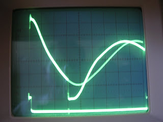
I've added the 12V accessory battery as an output load and let things settle. This picture shows the gate drive (Vgs) of one FET (bottom left) and the resulting source-drain voltage (Vds) on the opposite FET. Time dimension is 5us/div. Note that the pulses going to the FET gates are 15us apart, causing the snap to a low voltage three divisions into the display. The Vgs pulse is still about 1.2 usec wide.

Here's the same image as above, but with a 7 amp load. The SG3525A is now pulsing the FETs much more often to handle the load. The gate-drive pulses are now 8us wide and the drain-source voltages are clearly jumping from zero volts to 156 volts to 312 volts.
The circuit controlling this pulse width is the opto-coupler feedback going into the inverting input on the SG3525A. As the load increases, the main output voltage tends to drop, telling the 741 op-amp to turn off the 4N25 opto-coupler. With the opto-coupler off, the inverting input for the error amplifier in the SG3525A falls and increases the pulse width. (See schematic in previous blog posting)
What boggles me about this picture is that this DC-DC converter was supposed to put out 400 watts. That's about 28 amps. Just pulling 7 amps causes the gate drive pulse width to increase to 8us which is over half of the available 15us time that they can be on. If I add another 7 amp load, the gate pulse width extends out to its full width of 15us and then the waveforms go a bit nuts. It seems to me that if we run out of controllable pulse width at 14 amps, then the controller has no way of providing anywhere near 28 amps. Hmm....

Another circuit I analyzed was the amperage control circuit. This circuit captures current going through the isolation transformer and converts it to voltage pulses. If these pulses get too high then the SG3525A controller should turn off the FET gate drives to prevent them from overheating. The top waveform in the above picture shows the voltage across the "Amps Adjust" potentiometer with just the 12V accessory battery load. Note that the primary signal shows nice rolling pulses; however, there are sharp spikes at every gate drive transition. These rolling pulses are supposed to control the nShutdown pin on the SG3525A controller. The unfortunate thing is that the actual voltage triggering the nShutdown pin are the voltage spikes. I believe the dimensions are 0.5V/div for the top waveform and 5us/div timebase.

Here's that same picture with a 7 amp load. The bottom waveform shows the FET gate drive pulses widening out to 8us and the voltage on the "amps adjust" pot show a much higher voltage (with much higher spikes too). I really need to get rid of those spikes.
I'm unsure of where to go next. It's clear to me that the 312 volts across the FETs along with the inductive kick-back spikes are running very near to the operating point of the FETs. At high current pulls, the inductive spikes are only going to get worse and tend to blow the FETs. I'm also concerned that a 7 amp load consumes just over 50% of the available pulse width modulation range for the gate-drive pulses, so we just can't supply more than about 13 amps without maxing out.
My first step is to try and reduce the inductive spiking. The only circuit provided for that is the C7/R16 capacitor/resistor pair between the FET drain posts. I found a great article on how to pick these values on the Maxim website here:
http://www.maxim-ic.com/appnotes.cfm/an_pk/3835
I also might add an RC filter to the "amps adjust" circuit to filter out the high-voltage spikes so that the nShutdown input gets a more accurate voltage.
I still haven't heard back from CCpower about this, but I'll give them a few more days. As you might imagine, I'm rather frustrated that I have to debug someone else's design. I'm not sure this component was meant for this application.
Subscribe to:
Posts (Atom)